Bit Error Test & Arbitrary
Waveform Generation

NRZ and PAM BPG
NRZ and PAM EA
AWG
Remote-Heads
Equalizers
Support
NRZ & PAM Pattern Generators (BPG)
SHF’s BPG instruments support a vast number of speeds, signal types and channel configurations. By extending the binary generators with our remote heads the data rate, the number of levels or both is increased. Just load the full data sheet by clicking the product number.
| wdt_ID | BPG | Remote-Head | Remote-Head Type | Focus Application | Max. Baud Rate | Max. Channels | Capabilities |
|---|---|---|---|---|---|---|---|
| 2 | SHF 12106 A | NRZ up to 60/64 Gbps | 64.0 | 4 | - NRZ up to 64 Gbps per channel - 1, 2, or 4 channel configuration - Ideal source for SHF remote-heads - Synchronization of multiple systems |
||
| 4 | SHF 12106 A | SHF 616 C | PAM-MUX | PAM4 up to 256 Gbps | 128.0 | 1 | - PAM4 up to 256 Gbps per channel - NRZ up to 128 Gbps per channel - Synchronization of multiple systems |
| 6 | SHF 12106 A | SHF C911 A | 67 | 4-Bit DAC | PAM4 up to 120/128 Gbps | 64.0 | 2 | - PAM-X with up to 64 GBaud - E.g. 128 Gbps PAM4 per channel - E.g. 64 Gbps NRZ per channel - Synchronization of multiple systems |
| 9 | SHF 12106 A | SHF C603 B | MUX | NRZ up to 120/128 Gbps | 128.0 | 2 | - NRZ up 128 Gbps per channel - 1 or 2 channel configuration - Synchronization of multiple systems |
| 10 | SHF 12124 B | NRZ up to 32 Gbps | 32.0 | 2 | - NRZ up to 32 Gbps per channel - 2 channel configuration - Both channels are synchronized |
||
| 17 | SHF 19120 C | NRZ up to 12.5 Gbps | 12.5 | 4 | - 4 NRZ channels up to 12.5 Gbps - Additional AWG outputs (2.85 GSa/s) |
NRZ and PAM Error Analyzers (EA)
By combining the SHF 11104 A EA with a SHF 11221 A DEMUX, the serial data rate is extended to up to 120 Gbps per channel. The SHF 11220 A PAM-Sampler enhances the capability for true PAM4 BER measurements to a speed of up to 58 GBaud PAM4 (112 Gbps). Just load the full data sheet by clicking the product number.
| wdt_ID | PN | Remote-Head | Remote-Head Type | Max. NRZ Data Rate | Max. PAM4 Baud Rate | Required Mainframe | Application Examples |
|---|---|---|---|---|---|---|---|
| 4 | SHF 11104 A | 64 | 32 | SHF 10001 C | NRZ up to 64 Gbps and PAM4 up to 32 GBaud (64 Gbps) | ||
| 16 | SHF 11104 A | SHF 11221 A | DEMUX | 120 | 32 | SHF 10001 C | NRZ up to 120 Gbps |
| 17 | SHF 11104 A | SHF 11220 A | PAM-Sampler | 64 | 58 | SHF 10001 C | PAM4 up to 58 GBaud (116 Gbps) |
Arbitrary Waveform Generators (AWG)
SHF is offering a cost effective solution housed in a small and light weight chassis (the SHF 19120 C) and a solution based on our BPG-DAC combination. Just load the full data sheets by clicking the product number.
| wdt_ID | AWG / BPG | Remote Head | Channels | Sample Rate | Vertical Resolution | Sample Memory |
|---|---|---|---|---|---|---|
| 1 | SHF 19120 C | 3* | 2.85 GSa/s | 14 bit | 1 GSa | |
| 2 | SHF 12106 A | SHF C911 A | 67 | 1 | 64 GSa/s | 4 bit | 16 GSa |
* Only one AWG channel accessible at a time. In addition there are four BPG outputs (1… 12.5 Gbps).
Remote Heads (MUX, DAC, PAM-MUX, …)
SHF remote heads can extend the functionality of our BPGs and EAs to higher baud rates and to more signal levels, essentially enabling higher data rates. Together with SHF devices, they form an enhanced-capability instrument. They can also be operated as individual units to upgrade existing setups. Simply apply the filter to narrow down potential remote heads, and access the comprehensive data sheet by clicking on the product number.
| wdt_ID | P/N | Type | Input | Output | Max. NRZ or PAM4 Speed | Type |
|---|---|---|---|---|---|---|
| 1 | SHF 614 C | 60 GBaud 6-Bit DAC |
1… 60 Gbps binary at 2 to 6 inputs |
1… 60 Gbaud 4 to 64 levels |
120 | Digital-to-Analog Converter (DAC) |
| 2 | SHF 615 B | 60 GBaud 3-Bit Power DAC |
1… 60 Gbps binary at 2 or 3 inputs |
1… 60 Gbaud 4 or 8 levels |
120 | Digital-to-Analog Converter (DAC) |
| 3 | SHF C911 A | 32 | 32 GBaud 4-Bit DAC |
5… 32 Gbps binary at 2, 3 or 4 inputs |
5… 32 Gbaud 4, 8 or 16 levels |
64 | Digital-to-Analog Converter (DAC) |
| 4 | SHF C911 A | 67 | 67 GBaud 4-Bit DAC |
5… 67 Gbps binary at 2, 3 or 4 inputs |
5… 67 Gbaud 4, 8 or 16 levels |
134 | Digital-to-Analog Converter (DAC) |
| 5 | SHF 602 B | 60 Gbps 4:1 MUX |
1.5… 15 Gbps binary at 4 inputs |
6… 60 Gbps binary at 1 output |
60 | Multiplexer (MUX) |
| 6 | SHF C623 B | 120 Gbps 1:2 DEMUX |
10… 120 Gbps binary at 1 input |
5… 60 Gbps binary at 2 output |
120 | Demultiplexer (DEMUX) |
| 7 | SHF 11221 A | 120 Gbps 1:2 DEMUX |
60… 120 Gbps binary at 1 input |
30… 60 Gbps binary at 2 output |
120 | Demultiplexer (DEMUX) |
| 8 | SHF C603 B | 128 Gbps 2:1 MUX |
2… 64 Gbps binary at 2 inputs |
4… 128 Gbps binary at 1 output |
128 | Multiplexer (MUX) |
| 10 | SHF 616 C | 128 GBaud PAM4 Multiplexer |
1.5…64 Gbps binary at 4 inputs |
6…256 Gbps PAM4 (3…128 GBaud) |
256 | PAM4-Multiplexer (PAM-MUX) |
| 11 | SHF 11220 A | 60 GBaud PAM4 Sampler |
60…116 Gbps PAM4 at 1 input |
30…58 Gbps binary at 1 output |
116 | PAM4 Sampler |
Equalizer / Filter
SHF equalizers are analog finite impulse response (FIR) filters that significantly improve the quality of heavily degraded signals by equalizing transmission channels in high-speed data systems. On the transmit side, they can be used with a BPG to pre-compensate for channel distortions (pre-emphasis). On the receive side, the filters can be used to enhance the signal before applying it to an EA.
| wdt_ID | P/N | Type | Max. Data Rate | Further Media |
|---|---|---|---|---|
| 1 | SHF C683 A | Analog FIR Filter | 140 Gbps (70 GBaud) PAM4 70 Gbps NRZ |
Video |
| 2 | SHF C684 B | Analog FIR Filter | 200 Gbps (100 GBaud) PAM4 100 Gbps NRZ |
Support – BERT & AWG Instruments
Literature
blank
General Info
BERT for Ethernet, OC-768, CEI, InfiniBand and Fiber Channel
SHF’s Bit Pattern Generators (BPG) or Pulse Pattern Generators (PPG), Error Analyzers (EA) and remote heads form a Bit Error Ratio Tester (BERT) suite, which supports a vast number of different applications including high speed Ethernet rates like 100GbE, 200GbE, 400GbE and 1TbE.
The instruments support up to 8 independent channels broadband from < 10 to 64 Gbps. By combining these instruments with our multiplexer (MUX) and demultiplexer (DEMUX) modules, the serial data rate is extended further up to 120 Gbps per channel.
A PAM source is formed by attaching one of our digital-to-analog-converter (DAC) remote heads to the BPG. This way, the fastest commercially available speed on a single serial coaxial interface (128 GBaud / 256 Gbps) is achieved using our PAM-MUX extender head.
SHF’s capability for true PAM4 BER measurements up to a speed of up to 58 GBaud PAM4 (112 Gbps) is also the industries fastest.
Arbitrary Waveform Generation (AWG)
When it comes to signal generation an Arbitrary Waveform Generator (AWG) is the all-in-one device suitable for every purpose in Telecommunication, Optics, Medicine, Radar, Physics or even Quantum Computing.
Brochures
Application and Tutorial Notes
- Jitter Analysis using SHF 10000 Series BERT Equipment
A short description of jitter and a tour of the SHF software used for the measurements. Includes an outline of the theory involved. - DQPSK – Bit Error Test Solution
Provides a general overview of the optical DQPSK, the generic structure of the SHF DQPSK optical TX and RX modules and the application in conjunction with SHF’s 50 Gbps BERT System - Skew Control
This application note describes how the alignment of the output signals from the Pattern Generator SHF 12103A could be adjusted greatly over many bit periods (integer bit delay) and fine-tuned within tenth of a picoseconds (skew control). - Multi-Level Signal Generation using the Multi-Channel SHF 12103A
The objective of this note is to provide a simple guide on how to make the best use of the SHF 12103 A Quad-32, 4-channel 32 Gbps BPG, as a multi-bit data source, to realise 4-level electrical signals when used in conjunction with an external broadband power combiner. - Jitter Injection using the Multi- Channel BPG
This note presents the setup to allow injection of jitter using a SHF Bit Pattern Generator. It demonstrates that SHF BPG’s are jitter transparent, i.e. it correctly transfer jitter from the clock to the data output signal. This enables jitter tolerance tests as required by many telecommunication standards such as 100G Ethernet and 40 GBit/s OTN. - Multi-Channel BPG SHF 12103/4 A
The objective of this note is to provide a reference to illustrate how to make the best use of the truly synchronous features, dual bit rate bands, and multi-channel nature of SHF 12103A and 12104A BPGs. Hardware implementation examples are given towards the realization of many advanced system experiments.
Tutorial Notes
- Tutorial Note 3 – Broadband Communication Signals
Transmission bandwidth, PRBS signals, correct multiplexing and demultiplexing, eye diagrams, Q-factor, jitter, bit error rate, error analyzers. - Tutorial Note 4 – Basics of Optical Communication
Background information about optical detection, polarisation, chirp, dispersion and non-linear effects. - Tutorial Note 5 – Modulation Schemes
EA and LiNb modulators, ASK, BPSK and DPSK modulation.
FAQ
blank
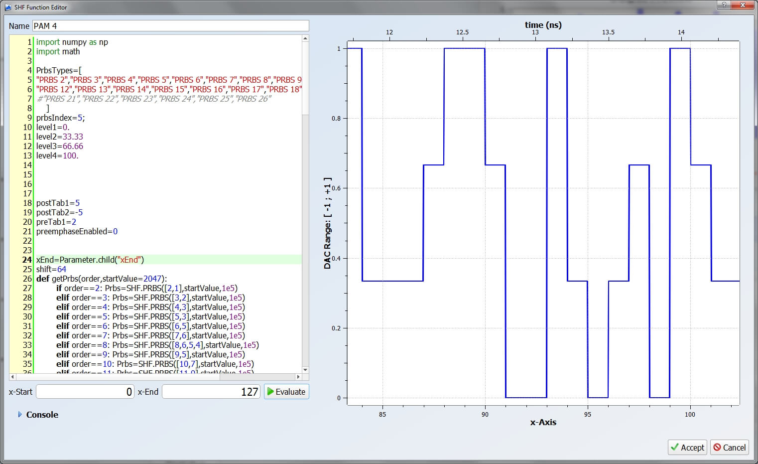
What makes a SHF BPG connected to a SHF DAC become a high baud rate AWG?
Because SHF 12104 A, SHF 12105 A and SHF 12106 A Bit Pattern Generators have
- multiple high data rate channels,
- individually programmable channels and
- channel synchronization
one can basically program any required output waveform from a DAC just by programming the input bits into the DAC accordingly.
Our new complementary software package, the SHF Control Center, assists the user to create the user patterns for any signal trace. With our SHF multi-channel BPG the software just needs to know which BPG output is connected to which DAC input and the arbitrary signal can be created.
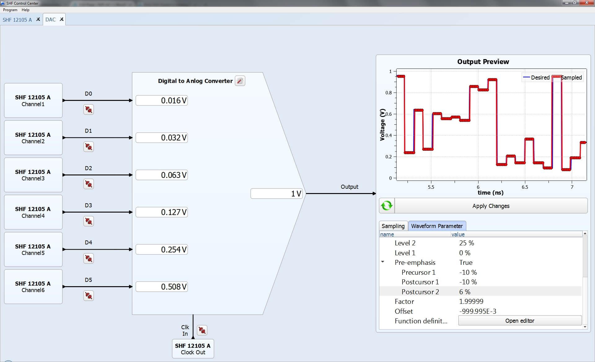
Above screenshot shows how the GUI is used to configure the multi-channel BPG SHF 12105A with a 6-bit DAC to form a PAM4 waveform with non-equal amplitude eye opening and pre-emphasis for device testing requiring some degree of non-linearity compensation.
How can I create an arbitrary waveform?
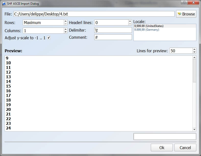
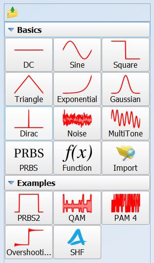
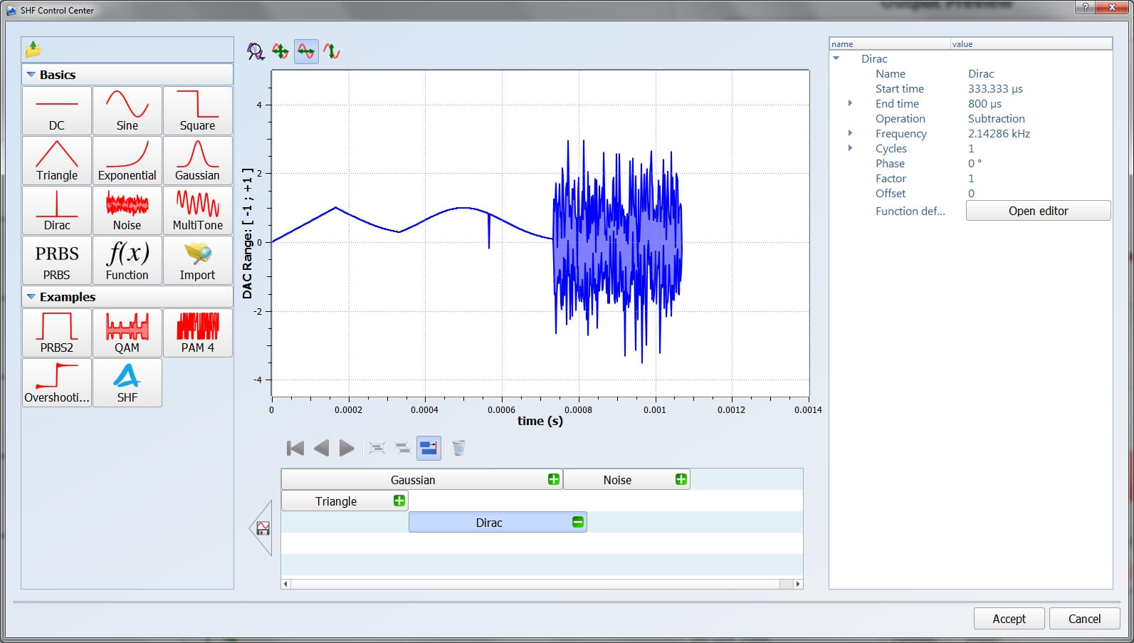
There are various options to create the waveform:
- Load it from a file
- Select from our library and change the parameters according to your needs
- Use the graphical sequence editor
- Program your waveform in our editor
One more click and the DAC will produce the desired waveform.
Can I generate single pulses or pulse trains?
Single pulses or pulse trains can be easily programmed and generated with the SHF 12106 A Bit Pattern Generator, resulting in pulse widths between 160 ps and 16 ps, and repetition rates between 128 ms and 1.28 s. Trains or sequences are transmitted seamlessly without a gap.
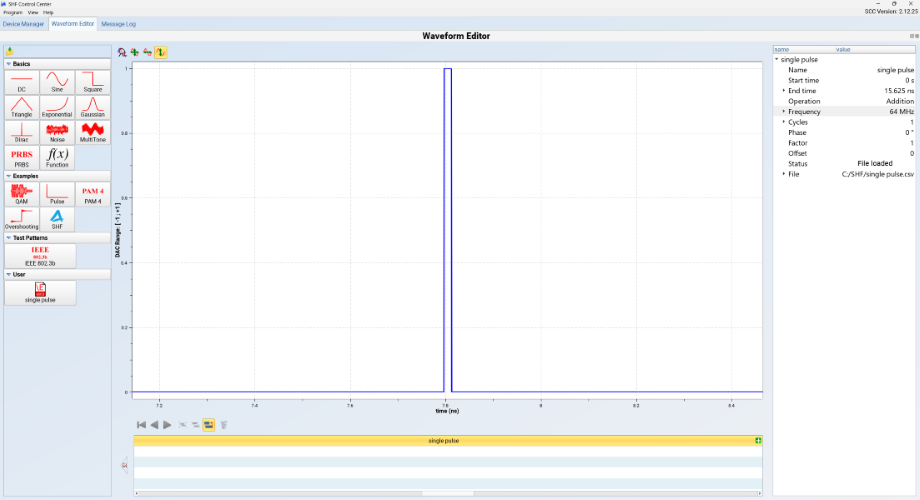
A single pulse in the SCC wavefor editor
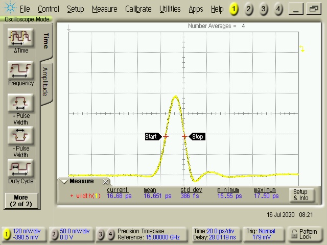
BPG output pulse: 500 mV peak, 17 ps width
The pulse amplitudes can be boosted up to ~10 V (more in our amplifier FAQ). This makes them suitable e.g. for controlling optical gates in quantum computing applications.
What are the benefits of a BPG-based AWG over conventional AWG?
Generally, a Bit Pattern Generator (BPG) has some advantages over an Arbitrary Waveform Generator (AWG):
A. Baud Rate = Sample Rate
BPGs operate very broadband by tuning the input clock frequencies (SHF BPGs work from approximately 5 Gbps up to 64 Gbps). The sample rate of an AWG can be restricted to a narrow band. This becomes particularly critical when data signals (be it NRZ or PAM) are to be produced where the sample rate of the AWG is not an integer multiple of the baud rate of the data signal.
With data signal created by a BPG + DAC architecture, the baud rate and the sample rate can always be identical (1 Sample per Baud), thus no software tricks have to be applied to compensate for fractional sample to baud rate relations.
B. Logical Pattern Generation (No Memory Used)
A BPG can produce some pattern types logically, i.e. not loaded from the memory (most famously, creating NRZ PRBS patterns). This way, the patterns can be very long (up to at least 231-1) and there is no up-load time (which can be quite long for long user defined patterns) as in the case of a conventional AWG relying on user-defined patterns.
In first place one may think that these advantages do only apply to pure BPG and not to an AWG based on a BPG/DAC architecture. For most microwave signals this is correct, however, for some data signals the coding can be done in the BPG hardware, thus the user memory is not used and above advantages do still apply for the signals from the DAC. Some examples are:
1.) Standard PAM
Just by applying standard PRBS signals to the DAC the DAC will create PAM4, PAM8 etc.
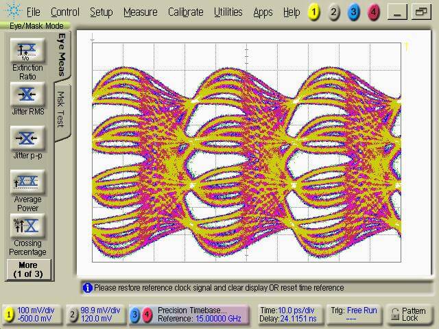
2.) Symmetrical unequal PAM4
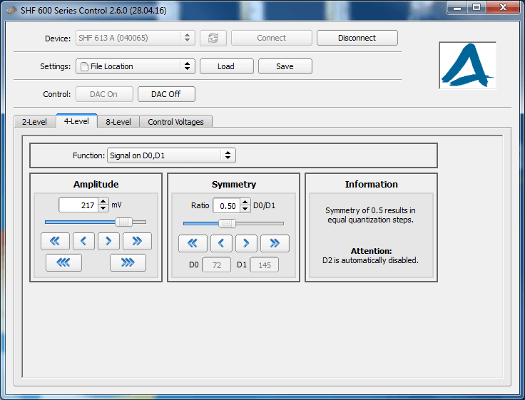
In case the voltage contribution of the LSB input is exactly half of the voltage contribution of the MSB, the PAM4 signal is fully symmetric, i.e. all three eye heights are the same. This would be the standard setting of the DAC.
If the voltage contribution of the input bits deviates from half, the eye heights won’t be equal anymore. However, it will always remain symmetric. This means, in case the inner eye gets bigger the two outer eyes will be smaller but the two outer eyes will always have the same height. In the SHF DAC GUI, this is defined by the symmetry control.
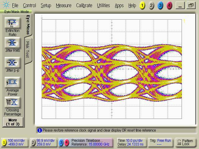
3.) Non-equal amplitude PAM4
With “non-equal amplitude”, all three eye heights are different. For example, the lowest PAM eye is small, the middle is average and the upper is big (or vice versa). This is quite useful in case the DUT has a non-linear transfer characteristic (e.g. an EA modulator).
With a SHF BPG and a SHF DAC with at least 3 Bits (the more bits you use the finer you can set your different eye heights), the individual level spacing can be set just by a few SHF Control Center clicks as shown below for the case of using a 3-bit DAC.
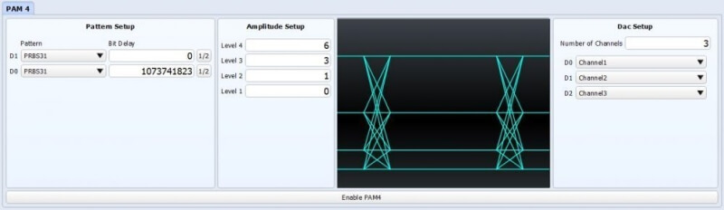
PAM4 Amplitude Setting
Please note, for this special application, you can leave the BPG in PRBS mode and let the BPG do the recalculation of the patterns in hardware. Thus there are no such AWG drawbacks such as pattern length restriction due to memory size limit, and waiting time when patterns are uploaded. Our architecture can do non-equal amplitude PAM eyes with pattern length up to 231-1.
4.) Pre-Emphasis
A pre-emphasis tap can be set up by generating the same data pattern twice with one being inverted and delayed (or advanced) by one bit before the patterns are added together. Delaying and inverting is a simple task for the multi-channel BPG while still being in PRBS mode. Adding together is done by the DAC. Even the amount of the pre-emphasis can be adjusted by varying the contribution of this input into the DAC.
In case enough bits are available at the DAC, this concept can be easily extended to multi-level signals and/or more pre-/de-emphasis taps.
Again, all this is done by simply generating standard PRBS patterns with the BPG and therefore “the AWG drawbacks” do not apply.
What does a DAC do logically?
A Digital-to-Analog Converter (DAC) is a device that converts digital data to an analog signal. It takes the binary input bits, weights and adds these together. Electrically SHF DACs do much more because of the on-chip 3R regeneration (re-timing, re-shaping & re-amplification) but logically this is the only operation a DAC does.
To have it less abstract, let’s assume a 3 Bit DAC in symmetric configuration (i.e. with equal amplitudes steps between the output levels) and for the sake of getting an overview, let’s normalize the voltage contributions. The output amplitude can be realized by adding the individual levels (basically it is just like counting binary). The table below shows a typical 3-Bit DAC scheme:
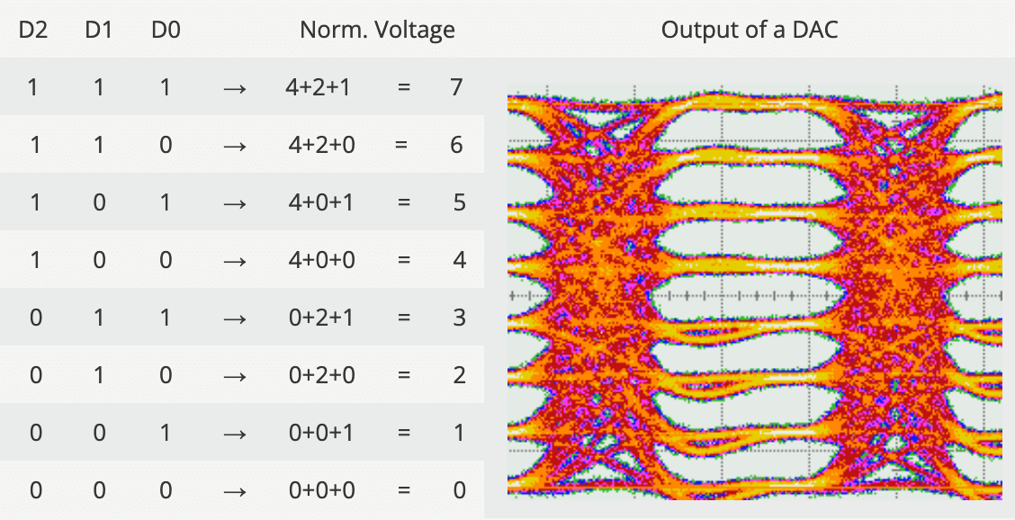
This scheme holds true for the 3-Bit DAC as above as well as for the 6-Bit DAC. However, for a 6-Bit DAC one has 26=64 instead of the 23=8 output levels shown above. There is no other difference between a 6 and a 3-Bit DAC. The more bits are used, the more levels the output has (with means greater resolution).
Can I use the SHF DAC with less input bits?
Yes, not all data inputs of the SHF DAC must be used. For example, in case a PAM-4 signal shall be generated only two data input signals must be applied to the DAC. All other inputs can be left floating.
Even operating the DAC as a binary D-type Flip Flop by using one input bit only is possible.
For such cases it is recommended to use the most significant bits of the DAC as these provide the biggest contribution to the output signal amplitude. In other words, the output amplitude is higher if the more significant bits are used and therefore the signal-to-noise ratio will be improved.
What voltage levels do I get from the DAC? Can I adjust the individual eye openings?
As an example, for a 3-Bit DAC, the relation between output voltage Uout and the input data D1, D2 and D3 is calculated as follows:
Uout=D0 · a0 + D1 · a1 + D2 · a2 .
In the data sheet of the SHF DACs you will find a table showing the maximum contribution of each bit similar as below:
| Input D2 | Input D1 | Input Do | Output Amplitude | Output Amplitude (example SHF 615 A) |
|---|---|---|---|---|
| on | a0max | 345 mV | ||
| on | a1max ≈ 2·a0max | 690 mV | ||
| on | a2max ≈ 2·a1max ≈ 4·a0max | 1380 mV | ||
| on | on | on | a0max + a1max + a2max | 2415 mv |
The amplitude contribution of each individual input Bit is adjustable by the appropriate slider in the GUI. The minimum voltage contribution anmin is half of the maximum anmax. As the DACs are calibrated, the voltage contribution in Volts is shown in the GUI.
To understand what implications this has on a PAM signal, lets assume the DAC is used in PMA-4 / 2-Bit Mode, i.e. the voltage contribution can be calculated as follows:
Uout=D1 · a1 + D2 · a2 .
For the PAM-4 signal this has the following implications:
- The output amplitude of a 3-Bit DAC in 2-Bit mode (one bit unused) is not as high as with all three bits used.
- If a1 & a2 are reduced by the same factor the overall amplitude gets reduced. By setting all contributions to the minimum the output power is reduced by 6 dB.
- If a1 is reduced (and/or a2 is raised) the inner of the three individual eyes gets bigger. In other words, the symmetry is changed. Please note, the symmetry cannot be changed in case all input bits are used.
- Adjusting all eyes individually (e.g. making the lower eye smaller, while enlarging the upper eyes) is not possible. Such unequal PAM signals can only be realized by programming the input bits accordingly. This would be a feature of a SHF BPG not the DAC itself (please see FAQ below).
The user does not have to worry about setting the individual voltage contributions. The symmetry and the amplitude for PAM-4 can be set in the GUI right away.
DAC GUI
What are the requirements for the input signals into the DAC?
SHF DACs require binary data inputs and a full clock signal.
The term ‘full’ clock means, that the speed of the clock (in Hz) must be the same as the speed of the input data (in bps). For example, to generate a 60 GBaud 8-level signal, one must apply a 60 GHz clock plus three 60 Gbps binary data signals to the DAC inputs.
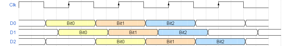
For proper operation all inputs must be (a) phase aligned and for some applications even (b) bit aligned. A perfect alignment is shown in the graphic below.
(a) Phase Alignment
All SHF DACs are active devices which re-time and re-shape the input signal. This makes the DACs very robust regarding signal impairments and skew at its inputs. Independent from the binary input signal quality one will always receive a perfect PAM signal even if the phase alignment is not as perfect as in the picture above. Nevertheless, the DAC needs to find a valid sampling point and therefore the clock & data input signals must be reasonably good aligned in order to meet the phase margin (hold time) requirements of the device. For example, if an input signal is sampled in its crossing the DAC will produce errors at its outputs.
Proper phase alignment for each single input can be easily verified by operating the DAC in one bit (binary) mode. In case the user has full control of the phase into the DAC (like with a SHF BPG) a perfectly aligned setup can be achieved easily.
(b) Bit Alignment
If above phase alignment requirement is fulfilled the DAC will always produce perfectly shaped PAM signals. For some applications, this is the only requirement one would need to consider.
In case of programming the DAC inputs in order to use it e.g. as an Arbitrary Waveform Generator (AWG) not only the phase alignment has to be considered but also the logical bit alignment. The graphic below shows input D2 is not properly bit aligned and should be shifted by -1 bit.
In case an error analyzer or a scope is used, there are straight forward possibilities to find out whether the bit streams are bit aligned (please be referred to the SHF literature). In addition, with a SHF 12104 A BPG one has full control of the bit alignment. Shifting D2 by -1 bit would be one click in the software and the DAC would have a perfect bit alignment.
What is the difference between passive combining and an active DAC?
It is possible to generate a PAM-4 signal by using a broadband passive combiner. However, this has many drawbacks compared to an active DAC module. Just a few to be mentioned:
Output Power
A DAC usually provides more output signal swing than a passive combiner since the least significant bit into the passive combiner must be attenuated accordingly (usually 6 dB).
Reflection
A passive combiner is transparent in all directions. This means, the signal applied to one input will be present not only at the output but also at the other input. This always has an influence on the output signal quality because multiple reflections impact the overall output signal quality accordingly (due to the imperfect output reflection coefficient (s22) of the driving source). Usually this influence is minimized by inserting attenuators at both pattern generator outputs. This however, further reduces the output voltage.
By using a DAC this problem can be disregarded. In contrary, even if you have a bad signal from your BPG the DAC will always provide a perfectly shaped output as long as it is good enough for sampling by the input latch of the DAC
Skew
The two signals into the passive combiner must be extremely well aligned as even a small skew between the input signals will distort the output signal. In case the used pattern generator does not have an internal fine skew control, an additional external delay line has to be added. This makes the passive combiner approach rather inconvenient.
Compared to the passive combining the DAC is extremely robust against skew between the driving signals.
Placement at the DUT
A passive combiner must be placed very close to the pattern generator outputs. This means, even if the combiner provides a reasonable good PAM-4 signal it must probably be transmitted through a long cable to the DUT. This will distort the high speed multi-level signal.
The DAC can be placed very close to the DUT. The extension cables can be inserted between the pattern generator’s outputs and DAC. The signal impairments introduced by these cables will not influence the DAC’s outputs as the input DFFs retime and reshape the signal on-chip before the voltage contributions are combined. After all, the DAC is much more robust and can be physically moved on the laboratory bench without any influence on the signal quality.
Additional Levels
SHF DACs have at least three input bits. The SHF 614 A even has six. With this additional bits one can do much more than just ordinary PAM-4. Examples are unequal amplitude PAM, PAM-5/8/16/../64, PAM with pre-emphasis. With a passive combiner all this is impossible.
Can a DAC be used to generate PAM-4 with Pre-Emphasis?
Yes, below you will find a simple schematic how this can be done e.g. by utilizing a 4-Bit DAC.
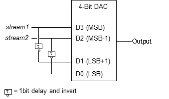
In case a SHF BPG with four outputs is available one can set the bit delay and invert the channel just by a few clicks in the software. No additional hardware is required.
In case an SHF BPG with ‘only’ two channels is available the data bar outputs can be used for D0 and D1. Here, external components have to be used for the one bit delay.
Pre-emphases can be a very powerful tool. In the example below a 30 GBaud PAM-4 signal is transmitted through a 2.5 meter SMA cable.
Input signal without pre-emphases
Output signal without pre-emphases
Input signal with pre-emphases
Output signal with pre-emphases
Videos
blank
Equalization of PAM4 signals
56 GBaud PAM4 BER analysis
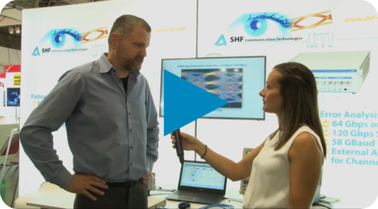
PAM signal generation at the ECOC 2017
With this DAC and the SHF 616 A PAM4-Multiplexer we show the generation of various types of high speed (56 GBaud and 112 GBaud) PMA4 signals like PAM with pre-emphasis or PAM with unequal eye openings.
Software
blank
SHF Control Center (SCC)
All parts in our current product range of Bit Error Test & Arbitrary Waveform Generation Instruments require the SCC to operate (e.g. the SHF 12106 A BPG). Some obsolete parts of older vintage, however, may require the BCC.
This SHF software is free of charge for the lifetime of your device. The most current version can be downloaded here.
BERT Control Center (BCC)
The BCC may be required to operate some older vintage obsolete parts of the Bit Error Test & Arbitrary Waveform Generation Instruments section.
Discontinued Products
blank
Discontinued Pattern Generators & Error Analyzers
| P/N | Type |
|---|---|
| SHF 11100 A | 6 … 50 Gbps Error Analyzer (OC-768) |
| SHF 11100 B | 6 … 56 Gbps Error Analyzer (OC-768) |
| SHF 11102 A | 3 … 28 Gbps Error Analyzer |
| SHF 11110 A | 40 Gbps Error Analyzer (OC-768) |
| SHF 11122 A | 40 Gbps Error Analyzer (OC-768) |
| SHF 11125 A | 2x 32 Gbps Error Analyzer |
| SHF 12100 A | 6 … 50 Gbps Pattern Generator (OC-768) |
| SHF 12100 B | 6 … 56 Gbps Pattern Generator (OC-768) |
| SHF 12101 A | 1.5 … 12.5 Gbps Pattern Generator (OC-192) |
| SHF 12102 A | 3 … 28 Gbps Pattern Generator |
| SHF 12103 A | 32 Gbps Quad- & 56 Gbps Dual-Channel Bit Pattern Generator (BPG) |
| SHF 12104 A | Multi-Channel 64 Gbps Bit Pattern Generator (BPG) |
| SHF 12105 A | Eight-Channel 64 Gbps Bit Pattern Generator (BPG) |
| SHF 12110 A | Multi-Band Bit Pattern Generator (OC-768) |
| SHF 12122 A | Multi-Band Bit Pattern Generator (OC-768) |
| SHF 12124 A | Dual-Channel 32 Gbps Bit Pattern Generator |
| SHF 12125 B | Multi-Channel 32 Gbps & 64 Gbps Bit Pattern Generator |
| SHF 12126 A | Multi-Channel 32 Gbps NRZ & 64 Gbps PAM4 Bit Pattern Generator |
Discontinued Optical Transmitters
| P/N | Type |
|---|---|
| SHF 5003 DPSK | E/O DPSK Transmitter |
| SHF 5003 RZ | RZ/NRZ Optical Transmitter |
| SHF 5003 NRZ | 50 GBit/s Optical Transmitter |
| SHF 46100 A | E/O conversion module |
| SHF 46120 A | ASK Optical Transmitter (E/O Converter) |
| SHF 46120 B | ASK & PAM Optical Transmitter (E/O Converter) |
| SHF 46120 C | ASK & PAM Optical Transmitter (E/O Converter) |
| SHF 46121 B | ASK & PAM Optical Transmitter (E/O Converter) |
| SHF 46121 C | ASK & PAM Optical Transmitter (E/O Converter) |
| SHF 46123 A | ASK & PAM Optical Transmitter (E/O Converter) |
| SHF 46210 B | 40 Gbps Optical multiformat DPSK Transmitter (E/O Converter) |
| SHF 46210 C | 40 Gbps Optical multiformat DPSK Transmitter (E/O Converter) |
| SHF 46211 A | 10 Gbps Optical multiformat DPSK Transmitter (E/O Converter) |
| SHF 46212 A | 40 Gbps Optical Duobinary Transmitter (E/O Converter) |
| SHF 46213 A | 40 Gbps DQPSK Optical Transmitter (E/O Converter) |
| SHF 46213 C | 40 Gbps DQPSK Optical Transmitter (E/O Converter) |
| SHF 46213 D | QPSK and QAM Optical Transmitter (E/O Converter) |
| SHF 46214 C | 100 Gbps DQPSK Optical Transmitter (E/O Converter) |
| SHF 46214 D | 110 Gbps DQPSK Optical Transmitter (E/O Converter) |
| SHF 46215 A | 128 Gbps DP-QPSK Optical Transmitter (E/O Converter) |
| SHF 46215 B | 132 Gbps (DP-QPSK) and 264 Gbps (DP-QAM) Optical Transmitter |
Discontinued Optical Receivers
| P/N | Type |
|---|---|
| SHF 5008 DPSK | O/E DPSK Receiver |
| SHF 47100 A | Optical Receiver |
| SHF 47100 B | Optical Receiver |
| SHF 47210 A | 39.8 to 43 Gbps DPSK Receiver w. single ended output |
| SHF 47211 A | 9.9 to 10,8 Gbps DPSK Receiver w. single ended output |
| SHF 47214 A | 48 to 55 Gbps DPSK Receiver w. single ended output |
| SHF 47215 C | 26 to 30 Gbps DPSK Receiver w. single ended output |
Discontinued 10000 Series Mainframes
| P/N | Type |
|---|---|
| SHF 10000 B | Large Mainframe |
| SHF 10000 C | Large Mainframe |
| SHF 10000 D | Large Mainframe |
| SHF 10001 A | Small Mainframe |
| SHF 10001 B | Small Mainframe |
Discontinued Amplifier Instruments
| P/N | Type |
|---|---|
| SHF 58211 A | Dual Amplifier |
| SHF 58214 A | Multi-Channel Amplifier |
| SHF 58215 A | Multi-Channel Amplifier |
Discontinued Arbitrary Waveform Generation Products
| P/N | Type |
|---|---|
| SHF 19120 A | 2.85 GSa/s AWG + 4x 10.3 Gbps BPG |
| SHF 19120 B | 2.85 GSa/s AWG + 4x 10.3 Gbps BPG |
Discontinued Multiplexers (Mux) & Demultiplexers (Demux)
| P/N | Type |
|---|---|
| SHF 1037 Mux | 25 Gbps 2:1 multiplexer |
| SHF 404 Mux | 60 Gbps 4:1 multiplexer |
| SHF 408 Mux | 100 Gbps 2:1 multiplexer |
| SHF 423 Mux | 60 Gbps 1:4 demultiplexer |
| SHF 5002 A | 60 GBit/s 1:4 Demultiplexer |
| SHF 5005 A | 60 GBit/s 4:1 Multiplexer |
| SHF 602 A | 4:1 Multiplexer |
| SHF 601 A | 60 Gbps 2:1 MUX |
| SHF 603 A | 120 Gbps 2:1 MUX |
| SHF 621 A | 60 Gbps 1:2 DEMUX |
| SHF 623 B | 120 Gbps 1:2 DEMUX |
| SHF C603 A | 120 Gbps 2:1 MUX |
| SHF C623 A | 120 Gbps 1:2 DEMUX |
Discontinued Digital-to-Analog Converters (DAC)
| P/N | Type |
|---|---|
| SHF 611 A | 32 GBaud 3-Bit DAC |
| SHF 611 B | 32 GBaud 3-Bit DAC |
| SHF 611 C | 43 GBaud 3-Bit DAC |
| SHF 611 D | 32 GBaud 3-Bit DAC |
| SHF 611 F | 32 GBaud 3-Bit DAC |
| SHF 612 A | 32 GBaud 4-Bit DAC |
| SHF 613 A | 60 GBaud 4-Bit DAC |
| SHF 614 A | 60 GBaud 6-Bit DAC |
| SHF 614 B | 60 GBaud 6-Bit DAC |
| SHF 615 A | 60 GBaud 3-Bit Power DAC |
| SHF 616 A | 112 GBaud PAM4 Multiplexer |
| SHF 616 B | 128 GBaud PAM4 Multiplexer |
Discontinued Filters and Equalizers
| P/N | Type | Bandwidth |
|---|---|---|
| SHF C681 A | 6-Tap FIR Filter | up to 55 GHz* |
| SHF C681 B | 6-Tap FIR Filter | up to 55 GHz* |
| SHF C684 A | 6-Tap FIR Filter | up to 55 GHz* |
*Bandwidth depends on the set filter characteristic.
Discontinued Flip-Flops & Buffer Amplifiers
| P/N | Type |
|---|---|
| SHF 430 DFF | 50 Gbps D-type flip-flop |
| SHF 431 B | 55 Gbps D-type flip-flop |
| SHF 450 B | Limiting Amplifier |
| SHF 631 A | 56 Gbps D-type Flip-Flop |
| SHF 651 A | 56 Gbps Buffer Amplifier |