RF & Microwave Connectors, Adapters and Cables

Choose a selection or scroll down to view all
Coaxial RF Adapters
Flexible RF Cables
Semi-rigid RF Cables
Semi-flexible RF Cables
Coaxial RF Launchers
Coaxial RF Panel Adapters
Universal Wrench
Support
Coaxial RF Adapters
For several years, we collaborate with our Japanese partner, KMCO. Our clients can leverage KMCO’s exceptional proficiency in crafting RF connectors when utilizing our RF adapters. The broad product selection encompasses all coaxial connector interfaces ranging from 18 GHz to 145 GHz of bandwidth.

All in- and between series adapters with 0.8 mm, 1.0 mm, 1.35 mm, 1.85 mm (V), 2.40 mm, 2.92 mm (K), 3.50 mm as well as SMPM (Mini-SMP or GPPO™) can be configured at the link below.
Flexible RF Cables
Totoku’s coaxial TCF cable assembly series demonstrates outstanding flexibility while retaining phase stability across varying temperatures and bending conditions. The remarkably low attenuation is achieved through the utilization of silver-plated copper and E-PTFE with a low dielectric constant. A wide array of options, including precise phase matching (< 1 ps), right-angle connectors, and armoring, are at your disposal.

These cables support all coaxial connector interfaces up to 145 GHz. Custom lengths are available for all cables, catering to the specific requirements of each customer.
Semi-rigid RF Cables
Engineered for frequencies up to 110 GHz our semi-rigid cables are a manually bendable and retain the pre-bent shape until intentionally reshaped. The assemblies listed in the product configurator offer customizable lengths and shapes, making them the optimal solution for large-scale applications and system prototyping. Each cable assembly undergoes precise manufacturing, ensuring excellent physical length accuracy (phase-matched cables are available upon request).
Semi-flexible RF Cables
Compared to other types of coaxial cables (refer to the sections above), the semi-flexible types exhibit the ability to accommodate the smallest bending radius. They require less force for bending compared to its semi-rigid counterparts, making them easily installable in confined spaces through hand shaping at customer’s site. KMCO’s semi-flexible cable assemblies are engineered for frequencies up to 110 GHz, specifically designed for broad-spectrum measurements and system applications. Customization options, including precision phase matching, are also available for all cables, which can be tailored to any customer-specified length.
Coaxial RF Flange & Sparkplug Launchers
KMCOs coaxial launchers are designed to establish a connection between the PCB within an RF module and the external environment. The RF signal transmission through the housing can be achieved using either a glass bead or a dedicated pin. Our range includes Sparkplug or Falange type launchers, supporting frequencies of up to 110 GHz. These launchers are available with various coaxial interfaces, including 2.92mm (K), 1.85mm (V), or 1.00mm interfaces, providing flexibility to meet different connectivity requirements.
| wdt_ID | P/N & Data Sheet | Type | Connector | Gender | Connection to Circuitry via | Bandwidth |
|---|---|---|---|---|---|---|
| 1 | KPC100M311 | Flange Launcher | 1.0 mm | male | Connector Pin (included) | 110 |
| 2 | KPC100F311 | Flange Launcher | 1.0 mm | female | Connector Pin (included) | 110 |
| 3 | KPC185M302 | Flange Launcher | 1.85 mm / V | male | Glass Bead GB185 | 65 |
| 4 | KPC185F302 | Flange Launcher | 1.85 mm / V | female | Glass Bead GB185 | 65 |
| 5 | KPC292M302 | Flange Launcher | 2.92 mm / K | male | Glass Bead GB292 | 40 |
| 6 | KPC292F302 | Flange Launcher | 2.92 mm / K | female | Glass Bead GB292 | 40 |
| 7 | KPC185M301 | Sparkplug Launcher | 1.85 mm / V | male | Glass Bead GB185 | 65 |
| 8 | KPC185F301 | Sparkplug Launcher | 1.85 mm / V | female | Glass Bead GB185 | 65 |
| 9 | KPC292M301 | Sparkplug Launcher | 2.92 mm / K | male | Glass Bead GB292 | 40 |
| 10 | KPC292F301 | Sparkplug Launcher | 2.92 mm / K | female | Glass Bead GB292 | 40 |
Coaxial RF Panel (Bulkhead) Adapters
“Panel Adapters” are coaxial adapters designed for attachment to a panel, facilitating the connection of coaxial interfaces from the inner components of a module or instrument to the external environment. The “Front Panel Adapter” provides a coupling nut on the outside which allows hand tightening without the need for a torque wrench while the “Hermetically Sealed Panel Adapter” is specifically engineered for bulkhead connections in vacuum or cryogenic environments, ensuring a sealed and secure connection for electric circuitry to the external components.
All components are available with either 2.92mm (K) or 1.85mm (V) coaxial interfaces, providing flexibility to suit various connectivity needs. Comprehensive data sheets for each part can be accessed by clicking on the respective part number, enabling users to gather detailed information for their specific requirements.
| wdt_ID | P/N & Data Sheet | Type | Outer Conductor | Gender | Inner Connector | Gender | Bandwidth |
|---|---|---|---|---|---|---|---|
| 1 | KPC185MF PA | Panel Adapter | 1.85 mm / V | male | 1.85 mm / V | female | 65 |
| 2 | KPC185MM PA | Panel Adapter | 1.85 mm / V | male | 1.85 mm / V | male | 65 |
| 3 | KPC185FM PA | Panel Adapter | 1.85 mm / V | female | 1.85 mm / V | male | 65 |
| 4 | KPC185FF PA | Panel Adapter | 1.85 mm / V | female | 1.85 mm / V | female | 65 |
| 5 | KPC292MF PA | Panel Adapter | 2.92 mm / K | male | 2.92 mm / K | female | 40 |
| 6 | KPC292MM PA | Panel Adapter | 2.92 mm / K | male | 2.92 mm / K | male | 40 |
| 7 | KPC292FM PA | Panel Adapter | 2.92 mm / K | female | 2.92 mm / K | male | 40 |
| 8 | KPC292FF PA | Panel Adapter | 2.92 mm / K | female | 2.92 mm / K | female | 40 |
| 9 | KPC185FSMPMFDPA | Panel Adapter | 1.85 mm / V | female | SMPM | male (fd) | 65 |
| 10 | KPC292FSMPMFDPA | Panel Adapter | 2.92 mm / K | female | SMPM | male (fd) | 40 |
| 11 | SMAFF PA | Panel Adapter | SMA | female | SMA | female | 20 |
| 12 | KPC185MF FPA | Front Panel Adapter | 1.85 mm / V | male | 1.85 mm / V | female | 65 |
| 13 | KPC292MF FPA | Front Panel Adapter | 2.92 mm / K | male | 2.92 mm / K | female | 40 |
| 14 | KPC185FF HA | Hermetically Sealed Panel Adapter | 1.85 mm / V | female | 1.85 mm / V | female | 65 |
| 15 | KPC292FF HA | Hermetically Sealed Panel Adapter | 2.92 mm / K | female | 2.92 mm / K | female | 40 |
Universal Wrench
When applying a torque to the coupling nut of an installed coaxial connector, unintended rotation of the entire connector body may occur. This can be prevented by stabilizing the connector body with the SHF UW145 A “Universal Wrench”.
| wdt_ID | P/N & Data Sheet | Wrench Sizes |
|---|---|---|
| 1 | SHF UW145 A | 8.0 mm, 7.1 mm, 6.5 mm, 6.35 mm, 6.0 mm, 5.5 mm, 5.0 mm & 3.5 mm |
Support – RF Connectors & Cables
Literature
blank
General Info
RF adapters, microwave cable assemblies and high frequency connectors up to 110 GHz can be supplied by SHF. Our partners KMCO and Totoku are located in Japan and provide excellent product quality, competitive pricing and fast delivery.
Tailored to Your Needs
All parts will be manufactured on customer request. This enables us to provide all cables exactly tailored to the customers demand (any user specified length and bend is available) while keeping the delivery time at 3 weeks.
Phase & Lengths Matching
Optionally we offer phase or delay matched versions of any cable. These extremely accurate manufactured cables are the ideal tool for transmitting complementary data streams or achieving a well defined bit delay, e.g. for decorrelation of data streams in DQPSK applications. The phase matching is possible to any reference value (e.g. bit delay, reference cable or transmission time).
Cryogenic Applications
Some of our coaxial components are designed and approved for cryogenic and vacuum environments. An example for custom designed semi-rigid cables for cryogenic applications can be found here.
Brochures
Application and Tutorial Notes
- Tutorial Note 2 – Microwave Connectors
Types of connectors, compatibility, specifications, care and cleaning.
Cables for Cryogenic Applications
FAQ
blank
Which connectors are compatible?
Below you will find the interface mating dimensions of different KMCO RF connectors. Whether a high quality male and female connector can mate together without any mechanical harm depends on the dimensions c, d, e, f, g and the thread type.
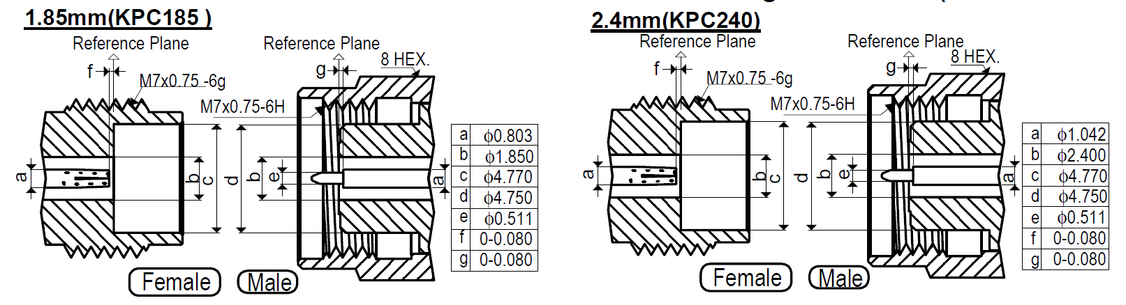
The table below shows IEEE-std-287 RF connector standards and the combinations which share the same specifications for the dimensions c, d, e, f, g and the thread type. Thus, these are mechanically compatible.
| wdt_ID | Connector | Compatible to |
|---|---|---|
| 1 | SMA | SMA, 3.50 mm & 2.92 mm |
| 2 | 3.50 mm | SMA, 3.50 mm & 2.92 mm |
| 3 | 2.29 mm | SMA, 3.50 mm & 2.92 mm |
| 4 | 2.40 mm | 2.40 mm & 1.85 mm |
| 5 | 1.85 mm | 2.40 mm & 1.85 mm |
| 6 | 1.00 mm | 1.00 mm |
| 7 | 0.80 mm | 0.80 mm |
Although mechanically compatible, the different interfaces still have different dimensions of the inner and outer connector (the dimensions a and b). Mechanically, this means that a conductor with a larger diameter connects with a smaller diameter conductor. The junction is not as smooth as if two connectors of the same type would mate. This “impurity” does influence the electrical performance. However, practically this influence is very small. In particular for data signals it is not noticeable.
IEEE-std-287 defines the interface names according to the inner diameter of the outer conductor (dimension b). Some manufactures, however, designate parts with their own names. These are not different connector standards; just different names. Thus they mate perfectly. The list below shows which designations are essentially referring to the same interface.
2.92 mm = K
1.85 mm = V
1.00 mm = W1
SMPM = Mini-SMP = GPPO™ = SSMP
Can I work beyond the specified bandwidth or even cut-off frequency?
The term ‘cut-off frequency’ originally comes from waveguides. A waveguide structure has a low-frequency cut-off; it guides waves at frequencies above the cut-off frequency with minimal loss. Wave guides do not have an inner conductor.
The performance of coaxial structures is primarily determined by the connector diameters and the dielectric material.
At low frequencies, electrical signals propagate in coaxial lines in the TEM (transversal electromagnetic) mode. However, if the frequency of a signal entering a coaxial line is too high, waveguide modes of the electromagnetic field (such as the TE11 mode) may exist and propagate. To ensure that only the TEM mode propagates and thus keep the signal undistorted, the operating frequency must stay below the cut-off frequency.
The cut-off frequency is not exactly equal to the specified upper frequency limit. In fact, as shown below, the standards leave some margin.
3.50 mm:
Upper Frequency Specification: 26.5 GHz
Cut-Off Frequency fc: 34 GHz
2.92 mm:
Upper Frequency Specification: 40 GHz
Cut-Off Frequency fc: 45 GHz
2.40 mm:
Upper Frequency Specification: 50 GHz
Cut-Off Frequency fc: 55 GHz
1.85 mm:
Upper Frequency Specification: 65 GHz
Cut-Off Frequency fc: 71 GHz
1.00 mm:
Upper Frequency Specification: 110 GHz
Cut-Off Frequency fc: 133 GHz
0.80 mm:
Upper Frequency Specification: 145 GHz
Cut-Off Frequency fc: 166 GHz
The onset of the first waveguide mode is characterized by a significant increase in insertion loss. When measuring beyond the cut-off frequency, the results become unreliable and inconsistent. Whether transmission through the device is subject to moding beyond the cut-off frequency is unpredictable, so is a VNA calibration beyond the cut-off frequency.
While connectors or cables can be operated beyond the cut-off frequency, the mixture of TEM and TE modes may result in unpredictable transmission and reflection parameters.
In some applications, such as those involving broadband communication signals, signal distortion caused by moding can be tolerated. The benefit can be lower attenuation due to the larger cable diameters.
Is it always the best to use the cable with the highest cut-off frequency?
- Cost: very small connectors are difficult to manufacture and therefore tended to be more costly
- Loss: smaller the connector geometry, higher the over-all cable loss caused by skin effect
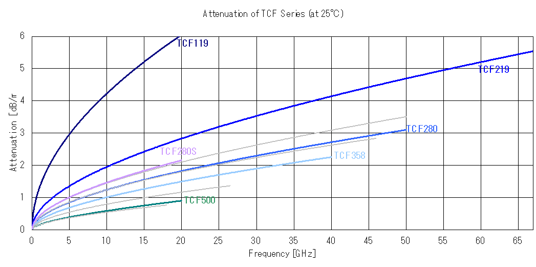
Attenuation of the TCF flexible cable assemblies series (click/touch to enlarge)
So, in particular for longer cables one might consider sacrificing bandwidth to minimize over-all loss of the transmission path. For example, SHF delivers its 64 Gbps Bit Pattern Generators with 2.40 mm cable assemblies although a cable with 1.85 mm connectors might provide more bandwidths.
Some connectors are available with different cables. Which cable shall I choose?
The Totoku cable line up below shows that some connectors can be attached to different cables. If above rule always applies, why would one do that?
1.
Because a cable can be equipped with two different connectors (like an adapter). The TCF280, for example, can be equipped with a 2.92 mm on one end and a 2.40 mm on the other end. Bearing in mind that such a combination results in the attenuation of a 2.40 mm cable while providing only the bandwidth of a 2.92 mm connector, such a cable can perfectly be used to omit an adapter.
2.
Because mechanical restrictions in the setup restrict the use of a bigger diameter cable.
Other than that, there is no reason to choose the thinner cable.
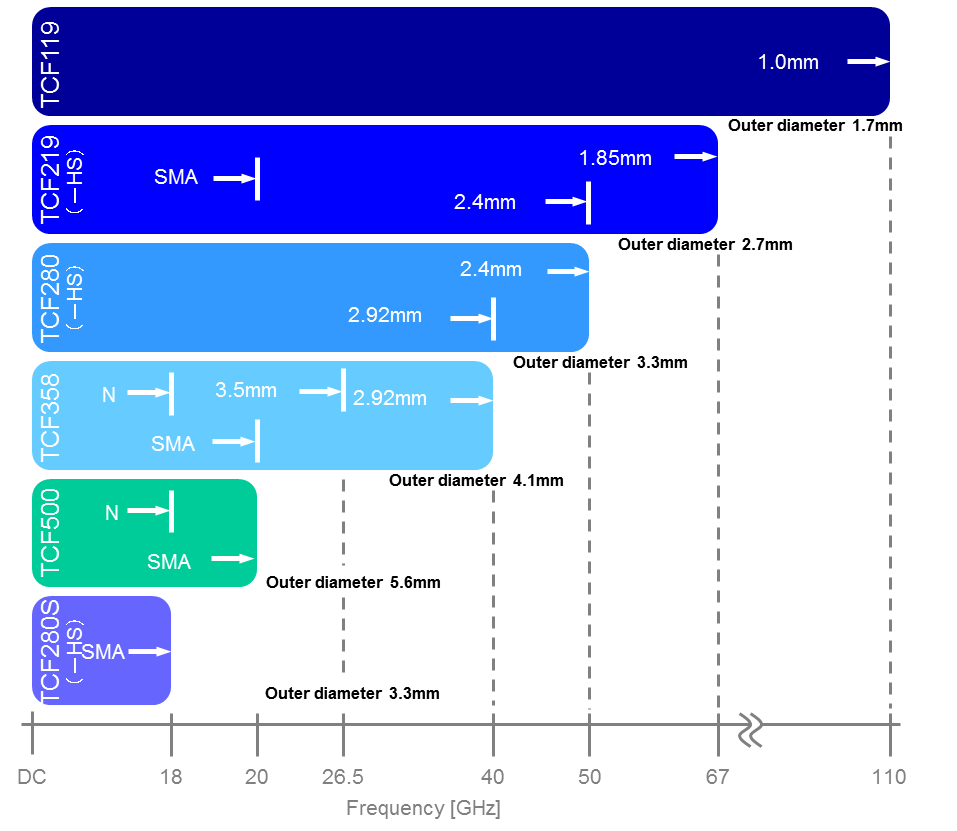
Totoku cable line up (click/touch to enlarge)