RF & Microwave
Broadband Amplifiers

All components are broadband, analog, and linear, making them well-suited for any RF and microwave signal amplification. This includes, but is not limited to, data signals, fast pulses, and radar applications. To shorten the list of potential amplifiers, please set your filter and load the full data sheet by clicking the product number (see notes).
wdt_ID P/N & Data Sheet Signaling Type BW Gain P1dB P3dB Max. PAM4 Eye Ampl.
1
SHF P101 A | ML
Single-ended
14
16
18
22
5.0
2
SHF P101 A
Single-ended
25
16
18
22
5.0
3
SHF P100 A
Single-ended
25
18
13
18
3.0
4
SHF P115 A
Single-ended
25
25
13
18
3.0
5
SHF S126 A
Single-ended
25
29
23
25
10.0
6
SHF D836 C
Diff. to SE
30
12
14
18
4.0
7
SHF M834 B
Single-ended
38
15
16
21
4.0
8
SHF S824 A
Single-ended
35
25
18
21
5.0
9
SHF D837 C
Diff. to SE
35
10
13
17
3.0
10
SHF M833 B
Single-ended
60
13
13
18
3.0
11
SHF F840 A
Differential (see notes)
55
11
10
10
2.0
12
SHF S807 C
Single-ended
55
23
15
19
4.0
14
SHF M804 C
Single-ended
66
22
12
16
2.5
15
SHF M827 B
Single-ended
66
11
12
16
2.5
16
SHF M827 B | 1.0 mm
Single-ended
70
11
12
16
2.5
17
SHF T850 C
Single-ended
100
11
11
13
2.0
19
SHF T854 A (NEW)
Single-ended
100
22
12
14
2.5
20
SHF T851 A
Single-ended
100
10
12
14
2.5
Notes:
- For simplicity, the values shown in the table might be typical values. For the guaranteed values, please refer to the data sheet.
- For binary signals, the amplifier can be driven towards saturation (practically the P3dB compression point).
- All power calculations for sinusoidal signals and Z = 50 Ohm.
- To compare with single-ended amplifiers, the power & amplitude of the SHF F840 A are specified for each arm of the differential output.
Support – RF Amplifiers
Literature
blank
General Info
Above you will find a selection of SHF broadband amplifiers, suitable for your 100G or 400G, 800G or 1.6T applications, fitting different drive requirements in complex signal generation based on Lithium Niobate or electro-absorption modulators. SHF amplifiers has been verified extensively for their excellent performance not only for NRZ but also with multi-level (e.g. for PAM or QAM) or analog signals (e.g. OFDM).
In the increasingly important field of quantum technologies, SHF amplifiers are widely used to amplify pulses with extremely short rise and fall times. To transmit entangled photons, some commercially available electro-optical components of ‘classical optical communication’ are being utilized. For example, in quantum key distribution (QKD) experiments SHF amplifiers proved to be well suited as optical modulator drivers as in any other high-speed data communication scenarios.
Brochures
Application and Tutorial Notes
- Tutorial Note 1 – Important RF and MW Parameters for Broadband Communication
Phase response, group delay, S-parameters, VSWR, noise figure.
FAQ
blank
Is the heat-sink included?
Yes, the heat-sink is always part of the delivery as a complementary item. In fact, it is mounted to the amplifier.
The heat-sink of an SHF amplifier can easily be removed by the customer. However, in that case additional cooling measures will be required. For example, the amplifier can be mounted onto a common metal plate with other modules, to provide the required cooling. If you find a SHF amplifier in your shelf, please assure that nobody else removed the heat-sink.
Can I amplify very low signal amplitudes?
Yes. However, the minimum signal level has to be above the equivalent input noise floor.
Every signal within the operating frequency range and below the input saturation voltage will be amplified with the gain specified in the data sheet. There is no such thing as an input threshold or similar.
For low signal amplitudes, however, another factor has to be considered: Noise.
The noise power Pnoise at a temperature T on every RF channel with a bandwidth of ∆f can be calculated with help of the Boltzmann constant k by:
Pnoise@input = k · T · Δf
This means, the noise power in dBm at room temperature (T=300 K) can be approximated by:
Pnoise@input = -174 + 10 log(Δf)
This is the noise at the input of the amplifier. This noise (as well as the signal) will be amplified by the amplifiers gain G. Further, the amplifier adds noise (this is given by the noise figure NF):
Pnoise@output = -174 + 10 log(Δf) + G + NF
To properly use the amplifier, the signal power at the output Psignal@output must be higher than the noise power Pnoise@output :
Psignal@output > Pnoise@output
Psignal@input + G > -174 + 10 log(Δf) + G + NF
Psignal@input > -174 + 10 log(Δf) + NF
Let’s assume a typical SHF amplifier with ∆f= 50 GHz and NF= 6 dB. For this amplifier one would need to provide a signal of more than -61 dBm (0.6 mV). Everything lower will vanish in the noise.
Typical noise figure of SHF families of amplifiers is approximately 5 dB at mid-band, unless otherwise specified.
Can I amplify single pulses?
Yes, SHF amplifiers can be used to amplify a fast single pulse.
Single pulses are considered to be unipolar. In this case, the maximum single pulse output amplitude is approximately half of the maximum square wave or PRBS output amplitude. (Please see FAQ ‘How does the AC coupling affect my signal?‘).
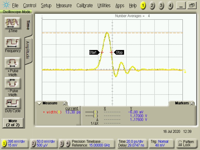
Fast Amplifier Output Pulse: 1.2 V peak, 13 ps width
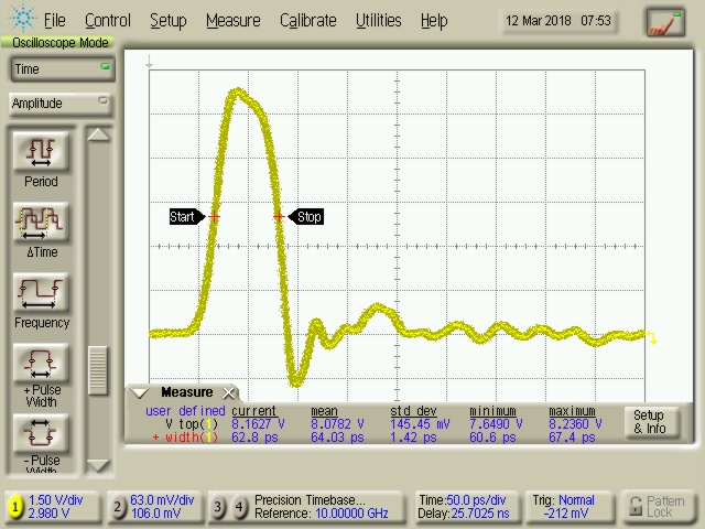
High-Amplitude Amplifier Output Pulse: 8.2 V peak, 63 ps width
How hard can I drive an amplifier to maintain amplitude linearity?
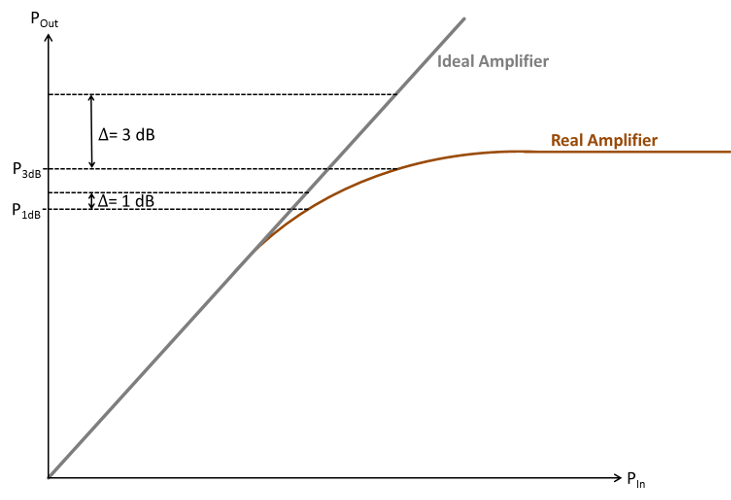
The gain given by the data sheet of the SHF amplifier is only valid for the linear region of the amplifier. Above certain input power levels the amplifier gets into compression and the gain POut/PIn is actually less than for input signals with lower power level.
To quantify this amplitude non-linearity, SHF specifies the compression points. The ‘x dB compression point’ is the output power at which the output level is x dB less than of an ideal (linear) amplifier.
Practically, the 3 dB compression point is very close to output saturation. In other words, the output power of the amplifier will not get higher even if the input power is further increased.
For binary signal, there is no problem driving the amplifier into the non-linear, saturated regime. The output signal simply gets ‘clipped’. In fact, sometimes this effect is beneficial as it can reduce the over- and under-shoot of the signal, resulting in a more rectangular output eye and improved rise and fall times.
For analog signals, however, amplitude non-linearity degrades the signal quality. In such case the amplifier has to be driven within its linear region.
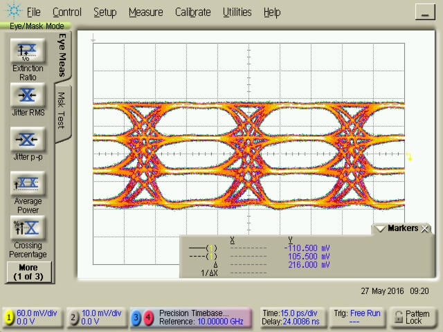
For PAM signals, for example, driving the amplifier into compression will result in a reduced eye height for the outer eyes. If this is not wanted, the amplifier has to be driven within the linear region.
As a rule of thumb, one should stay below the 1dB compression point P1dB. In addition, the table above lists the “maximum PAM4 eye amplitude.” This indicates when compression begins to affect the PAM4 signal displayed on a scope. Unlike P1dB compression, this value is measured with broadband data signals.
small signal input
output < P1dB
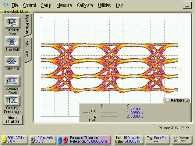
larger signal input
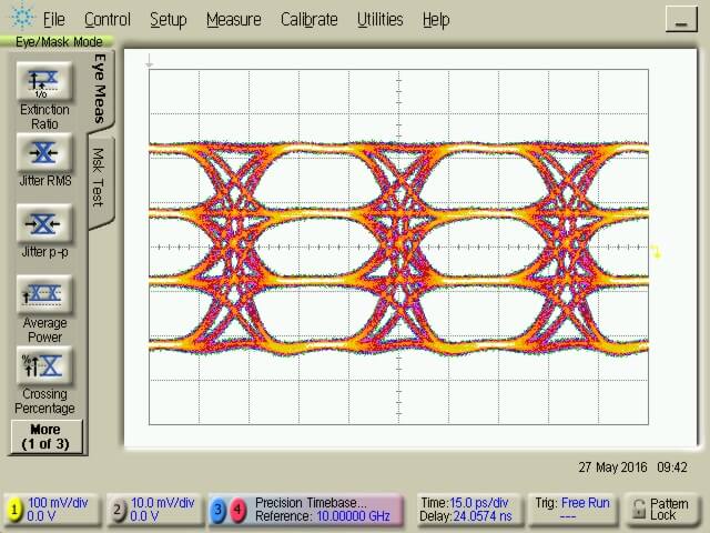
output > P1dB (outer eyes compressed)
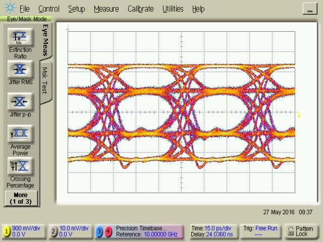
If higher output amplitude level is required, it is possible to pre-compensate for the amplifiers non-linearity. If, for example, the PAM signal is generated by an SHF DAC, it is possible to provide a signal with increased outer eye openings (pre-distortion), so the PAM signal at the output of the amplifiers, or even the E/O converters, is perfectly equal shaped.
larger signal input pre- distorted
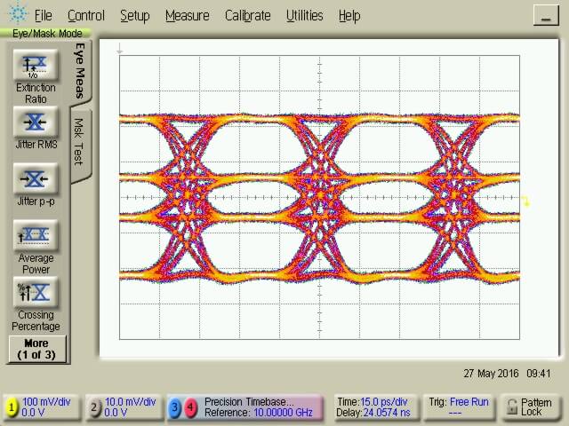
symmetrical output with amplitude > P1dB
What does the gain, output power and crossing control of SHF amplifiers actually do?
In case you do not use the control i.e. by not using the pin (leave it floating) or by not modifying the factory settings with a computer, the amplifier always provides maximum gain, maximum output power and ideal crossing.
In order not to mix up these three settings, a little explanation might be helpful:
Gain
A gain set to maximum results in the maximum available gain from the amplifier. In other words the amplifier will have the gain stipulated in the data sheet and on the label.
By using the gain control function one can reduce the gain continuously by up to 3 dB. This is intended to be used for fine tuning, as external attenuators in the range of 1 dB to 2 dB are not available with good performance at high frequencies. For attenuation ≥ 3 dB an additional external attenuator would be the recommended choice.
The gain control does only provide reduction of the output signal swing in case the amplifier is operated with small signal inputs. In other words, if your amplifier is clipping the signal because it is driven into saturation, there might be limited result from using the gain control as the maximum output power the amplifier can provide is not affected by this setting.
Output Power
In case the amplifier is driven into or towards saturation and the output signal swing shall be reduced the output power control shall be used. The output power control lowers the saturation levels (e.g. the 1dB, 2dB and 3dB compression points). This means, even with the output power reduced as much as possible a small signal gets amplified with maximum gain and is not reduced while larger signals get compressed earlier.
Driving the amplifier into saturation by reducing the output power can have a positive effect on binary signals. As the signal gets clipped on the top line the NRZ signal gets more rectangular. In fact, it may be that the output signal shows faster rise/fall times than the input. Further, unwanted ringing on the top line may be reduced.
If most linear amplification is required, on the other hand, it might be best not to reduce the output power as the linearity suffers from potential saturation effects (please be referred to above FAQ “How hard can I drive an amplifier to maintain amplitude linearity?”). On a PAM signal, for example, one will see a reduced eye opening of the top and bottom eye while the inner eye remains open.
Only with output power set to maximum the amplifier will have the output power as stipulated in the data sheet and on the label.
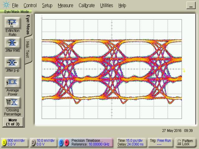
Crossing
All SHF amplifiers are AC coupled at the in- and output. As a result, in case the crossing control is not used, the output signal swings symmetrically around the 0 V line. By using the crossing control the operating point of the output stage transistor is modified in a way that the output signal swing is shifted either up (i.e. it swings around a positive value) or down (i.e. it swings around a negative value).
On a NRZ eye diagram one simply sees the crossing (i.e. the point where the rising and the falling edge are crossing each other) modified.
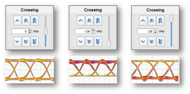
For most applications a 50% crossing is considered as ideal and thus all amplifiers are tuned in a way that if the crossing control is not used they provide 50% crossing. However, in cases where the DUT driven by the amplifier inadvertently shifts the crossing, the control can be used to pre-compensate so that optimum 50% crossing is achieved at the output of the DUT not at the output of the amplifier.
For PAM signals, the crossing control can be used to reduce the eye height of either the top or the lower eye(s). Again, this can be very helpful to compensate for non-linarites of another part (e.g. a laser).
What is the option MP (matched pair)? Can I use two amplifiers for a differential signal?
For all SHF amplifiers we offer the option matched pair (MP).
When choosing this option the two amplifiers of the pair will be matched to provide identical gain and propagation delay within the tolerance range. This is used very often, for example to transmit differential signals, but also for other applications where two signals have to drive a DUT synchronously (e.g. when driving an I/Q modulator).
How can I connect the SHF amplifier to my DC Power supply?
Which power supply do I choose?
An amplifier is an active device and thus needs a DC power supply to operate. Since all our amplifiers contain an internal voltage regulator and thus the DC supply voltage is not required to match exactly to the value stated on the top label at the appropriate pin, the supply can be taken from any regulated voltage source according to the individual amplifier’s data sheet.
How do I set my current limit?
When the recommended voltage as stated on the top label is applied, the typical current drawn is also stated on the label. However, the current may change with different voltages applied (effect of the internal regulation).
Further, the amplifier requires more current during start up. This is particularly important in case one sets the current compliance of a very fast acting voltage source. So, if the power supply features a current limit/compliance, that limit should be set to a higher value of up to 200% of the stated nominal operating current, so as to allow for an in-rush of current during start up.
How do I connect ground (GND)?
The amplifiers housing, the outer connector of the coaxial RF connectors as well as the GND pin are connected together (as with almost any other RF module or instrument). This means, prior to connecting the amplifier to the power supply, it must be connected to a common ground with the rest of your circuitry as otherwise transient currents may occur when connecting the amplifiers RF ports. This means:
- If a wall power supply is used, it usually does not feature a ground terminal and thus its output is floating. Therefore, the amplifier’s GND itself must be connected to the common/ground of the circuitry attached to the amplifier’s input and output.
- If a lab power supply which features a ground terminal is used and if that terminal is the common ground of the circuitry attached to the amplifier’s input and output, then the negative voltage output terminal (which connects to the amplifier’s GND pin) must be connected to this ground terminal.
How do I connect the pins?
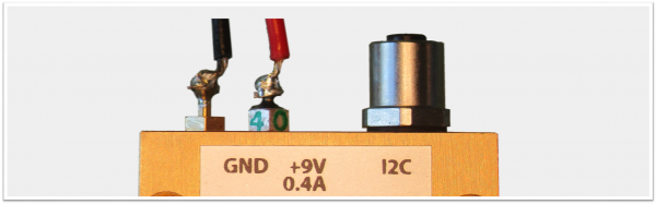
The supply connections can be made in a variety of different ways. The fastest way is to use fine test hook clips (e.g. Hirschmann Test & Measurement 932959001). As the housing is physically connected to the ground pin care has to be taken to prevent VDD from short circuiting to the housing or the ground pin. This may happen in case the probe is too big.
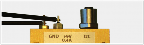 Supply Pins connected with Test Hooks
For a more permanent connection, soldering flexible cables with a diameter from 0.2 to 0.5 mm2 (AWG 24…20) is the recommended option. For the positive supply feed through filter (and, if applicable, the bias tee, gain and crossing control pins) a maximum soldering temperature of 260°C for 3 seconds shall not be exceeded. As the ground connector is directly connected to the solid housing, it requires significantly more heat.
 Supply Pins with Soldered Supply Connections
For the S, D and F series amplifiers (here the product code starts with a S, D or F) another alternative is to connect the supply cables to an IC socket with a 2.54 mm pitch. This can be pushed-on to the appropriate pins.
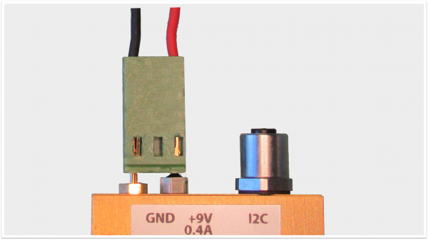 Supply Pins with Fitting IC Socket
How does the AC coupling affect my signal?
All SHF amplifiers are always AC coupled at the input and output. This means any DC voltage will be blocked, no DC current can flow, and the output of the amplifier will always be free of any DC content (unless the amplifier has a special option as per the FAQ below). “Free of any DC content” means, that the energy of the negative signal parts equals the energy of the positively directed signal parts. In other words, the area (integral) under the 0 V line on a scope equals the area (integral) above 0 V.
For data signals with equally distributed ‘1’s and ‘0’s it does just mean that the signal swings symmetrically around the 0 V even if the input into the amplifier was unidirectional. The same applies for other signals with 50% duty cycle: for example, a symmetric sinusoidal signal.
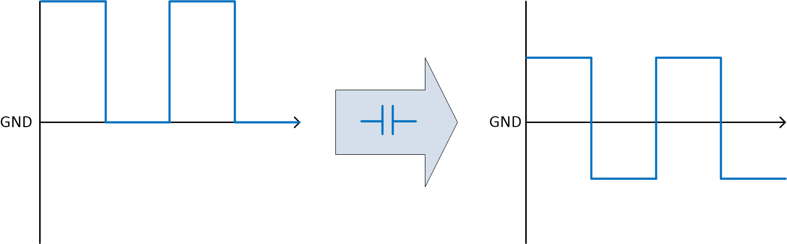
AC coupling of a signal with a 1 to 1 mark space ratio
For signals with a very low pulse/pause ratio. The shift may sometimes be hardly noticeable as the energy during the pause is spread over a long period (relative to the time of the pulse).
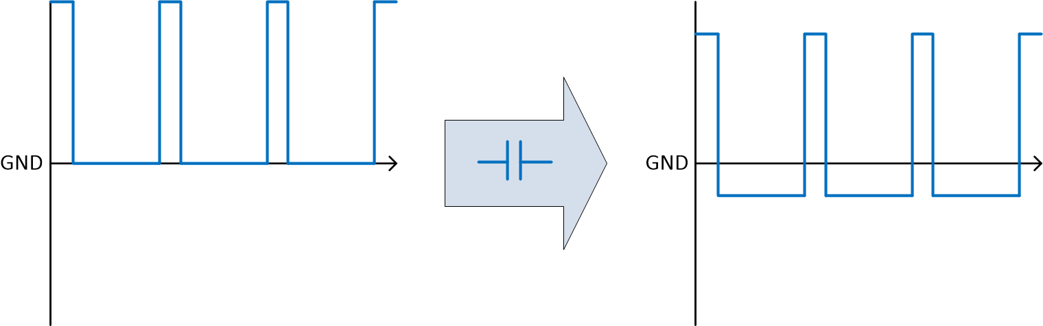
AC coupling of a signal with a 1 to 4 mark space ratio
In this respect, however, another effect must be mentioned. As SHF amplifiers are supposed to output signals symmetrically swinging around 0 V the signal swing we stipulate in our data sheets and labels assume the same. For example, an amplifier which can go up to 10 V peak to peak (saturation level) can swing from – 5V up to + 5V and an unidirectional pulse (a pulse only in negative or positive direction) can also not exceed this 5 V threshold.
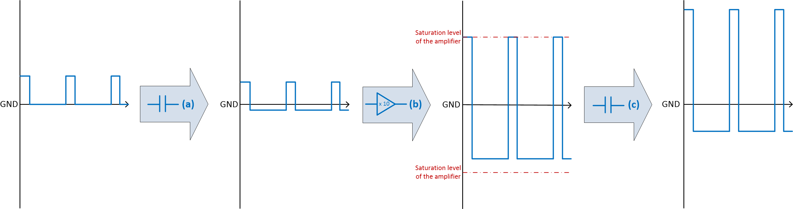
(a) AC coupling of a signal with a 1 to 4 mark space ratio (as above)
(b) Only the negative pulses are amplified by the gain factor of 10. Positive parts are clipped as the saturation level is reached.
(c) The DC level shifts again as the amplifier is not only input but also output AC coupled.
With some tuning measures (like the crossing control) one can shift this symmetry to a small extend. Please let us know if this is relevant for your application.
Measurements for different mark space rations showing the AC coupling and the clipping beahaviour of a real SHF amplifier are shown in this pdf report.
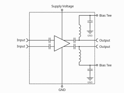
What is the Bias-Tee and the DC-Return Option?
Bias-Tee
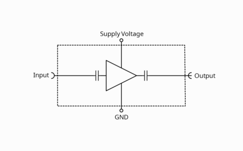
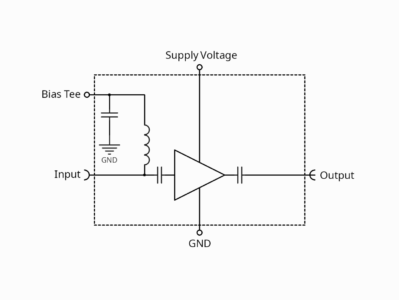
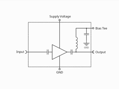
As explained in above FAQ SHF amplifiers are AC coupled. If the device connected to or after the amplifier needs a certain DC to operate a bias tee can be integrated into the amplifier to the input or output or both. With such Bias Tee option, the amplifier will have an extra pin where the DC can be applied.
Amplifier w/o Bias Tee
Amplifier w. Bias Tee at the Input
Amplifier w. Bias Tee at the Output
Differential Amplifier w. Bias Tee at the Output
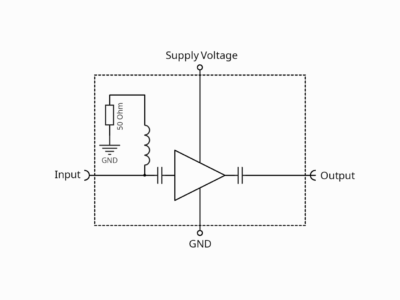
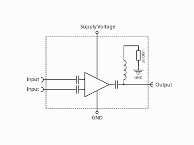
DC-Return
Another option would be the integrated DC-Return. Like for the Bias-Tee this can be integrated into the amplifier to the input or output or both. A DC-Return is a 50 Ohm return path to ground. This is required if the device connected to the amplifier needs a DC current to flow as -without the option- no DC current flow would be possible (due to the explained AC coupling).
The DC-Return path to ground is only required in case the connected device needs the explained current flow to operate. This applies for example to some photodetectors of former generations.
Amplifier w/o DC-Return
Amplifier w. DC-Return at the Input
Amplifier w. DC-Return at the Output
Availability
A DC-Return and a Bias-Tee cannot be integrated to the same output at the same time. However, if a Bias-Tee is already there it can be converted to be a DC-Return, just by connecting the bias tee pin to ground via a 47 Ohm resistor (as the internal impedance of the DC path is ~ 3 Ohm).
It has also to be mentioned that not all options are available for all amplifier types. Please be referred to the data sheet for the availability for particular amplifier modules.
Does SHF offer TIAs?
We do not offer TIAs.
A conventional TIA has an input impedance of 0 Ω, while our voltage amplifiers have an input impedance of 50 Ω.
However, SHF amplifiers can be used instead of TIAs.
An AC input current leads to an AC voltage drop across the 50 Ω input impedance. Therefore, the transimpedance of our amplifiers is 50 Ω multiplied by the voltage gain. If the signal source (e.g. a photodetector) requires a DC path to ground, an internal bias tee or DC-return can be used.
So, all our amplifiers work well with AC input currents. For example, the transimpedance of an amplifier with 20 dB gain (i.e. a linear voltage gain of 10) is
Z = 50 Ω x 10 = 500 Ω
While a conventional TIA has an input impedance of 0 Ω, our amplifiers have an input impedance of 50 Ω.
Software
blank
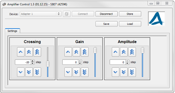
SHF Control Center (SCC)
For basic operation of an SHF amplifier, no software is required. However, the SHF Control Center (SCC) can be used to set the gain, output power and crossing of an SHF D, F and S-Series amplifier.
Please note that older versions of the SHF D-Series amplifiers are to be operated with the “SHF 600 Series Control”.
This SHF software is free of charge for the lifetime of your device. The most current version can be downloaded here.
SHF 600 Series Control
Apart from numerous modules from our High-Speed Data & Telecommunication Modules section the SHF 600 Series Control can be used to set the parameters of the SHF D836 A, SHF D836 B, SHF D837 A and SHF D837 B amplifiers. All other amplifiers are controlled by the SHF Amplifier Control.
Discontinued Products
blank
Discontinued Amplifiers
| P/N | Bandwidth |
|---|---|
| SHF 100AP | 25 GHz |
| SHF 100APP | 12 GHz |
| SHF 100BP | 25 GHz |
| SHF 100BPP | 12 GHz |
| SHF 100CP | 29 GHz |
| SHF 100CPP | 12 GHz |
| SHF 104P | 42 GHz |
| SHF 105C | 30 GHz |
| SHF 115AP | 25 GHz |
| SHF 115BP | 17 GHz |
| SHF 801P | 58 GHz |
| SHF 803P | 40 GHz |
| SHF 804EA | 45 GHz |
| SHF 804M | 65 GHz |
| SHF 804TL | 55 GHz |
| SHF 806E | 38 GHz |
| SHF 807 | 40 GHz |
| SHF 810 | 38 GHz |
| SHF 824 | 31 GHz |
| SHF 826H | 25 GHz |
| SHF 827 | 65 GHz |
| SHF D836 A | 30 GHz |
| SHF D836 B | 30 GHz |
| SHF D837 A | 35 GHz |
| SHF D837 B | 35 GHz |
| SHF L806 A | 40 Ghz |
| SHF L810 A | 38 Ghz |
| SHF M803 A | 55 GHz |
| SHF M804 B | 66 GHz |
| SHF M827 A | 67 GHz |
| SHF M833 A | 50 GHz |
| SHF M834 A | 34 GHz |
| SHF S804 A | 60 GHz |
| SHF S804 B | 60 GHz |
| SHF S807 | 50 GHz |
| SHF S807 B | 55 GHz |
| SHF T850 B | 100 GHz |